A lot of people ask me if it’s a good idea to stack the axial flux alternator with 3 magnet disks and two stators. I have done a page comparing the costs and performance of two alternators built using my recipe.

A lot of people ask me if it’s a good idea to stack the axial flux alternator with 3 magnet disks and two stators. I have done a page comparing the costs and performance of two alternators built using my recipe.
You can download it by clicking on the paragraph above. My Recipe Book has been updated enough, and I don’t want to make it bigger, and in any case I don’t have time to spell out this much detail for each of the six sizes, in both metric and ‘english’ units of measure. So I offer this as a supplement to those of you who choose the build machines of this specific size (an old favourite), and also as a source of ideas and clarification for people working on the other projects in the book.

The drawings show the actual length of each piece of metal, so you don’t have to look them up in a table amidst all the other sizes of turbine. I’ve also put in a couple of new hints and different ways to do stuff.
As ever I have been driven by trying to make the task as simple and cheap as possible whilst being strong and reliable. Of course there are any number of other ways to put it together using materials that you may have to hand, but this is based on a mimimal range of very standard steel sections.

Have fun, and feel free to send me comments and questions as always.
I have just done a service on our local Proven 6kW (aka Proven 11, aka Kingspan Wind KW6) at the Council’s School here on Scoraig. First time it has been taken down since 2006. Installed in 2003 by Sangsters.
Nothing much goes wrong with this particular turbine. The covers blew off in 2005, and this happened again last November (2011) and I finally got the go ahead to put them back on so I took it down yesterday, and sorted out a few minor issues. Greased the bearings, and replaced some plastic bits and bobs. Renewed the cable-ties and added a few to the covers. Cranked it back up on its 15 metre free standing pole today (took about 45 minutes with a 3200kg Tirfor).
Click on a photo to see it full size, with extra comments in some cases.
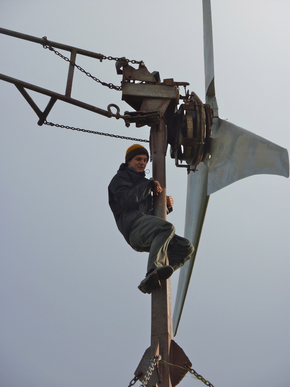
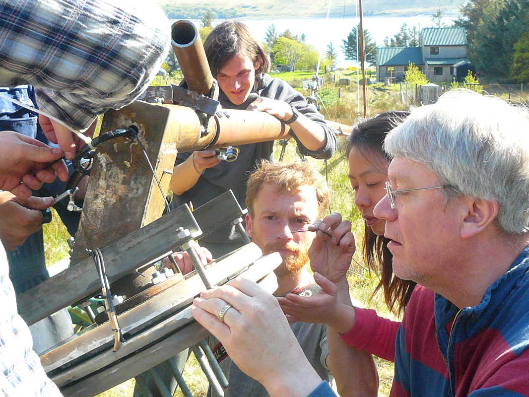
Last minute adjustments
Participants: 6 (Robert, Jonathan, Kostas, Benji, Yanti and Kern)
Dates: 5-12 May 2012 Location: Scoraig.
Project: 3 metre machine using ferrite/ceramic magnets at 24VDC
Poles: 10, (3 magnet blocks 50 x 50 x 20 per pole)
Coils: 12 (37 turns of 2 x 1.6mm wire)
Target cut in speed (recipe) 170 rpm
Application – the croft next door to me (for sale) on Scoraig. 24V system and 20 metre tower with dead Samrey prototype on it.
Accommodation the bunkhouse, Scoraig. Full-on home made food and frivolity.
 The following video shows Jonathan helping me to put Paul’s (green painted) blades onto the zebra turbine. We also increased the air gap a little to make sure the magnets did not rub on the stator. The cut in speed is a bit higher than I would normally choose for a 3 metre turbine (195 rpm for 24VDC) but it runs very smoothly, and will definitely not stall at least.
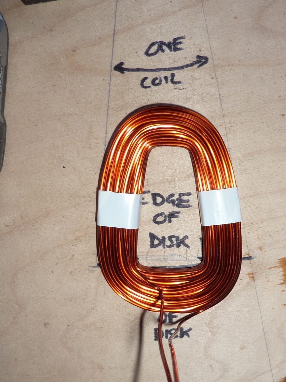
 Coils wound in pairs using 2-in-hand 1.6mm diameter wire. Each coil has 37 turns in the one we did for the workshop.
Coils in each pair are roughly ‘in phase’ if one is flipped over as shown. (Actually there is still 30 degrees of electrical phase difference between them, so they are each 15 degrees off the total combined phase angle, which means about 3.5% loss of voltage.)
Pairs that are opposite to each other are ‘in phase’ if connected backwards as shown above. Then the phases are connected in star by linking all of the starts to a neutral (black wires).
This alternator uses 10 poles made from ferrite magnets. When magnets are fitted tightly together like this it makes sense to me to use smaller coils with smaller holes and benefit from the shorter turns in each coil. It’s fun to try something different anyway.
The same winding could work with 14 magnets. But I see no merit in doing this. Maybe somebody can? The inner turns would get more induction from smaller poles, but there would be more leakage flux.
Here are some photos of the workshop. There were 8 participants plus me. We built a 2.4 metre diameter 24-volt turbine from the Recipe Book. Weather was great and we even got a little wind on Friday so the machine produced a few amps.
We made the magnet rotor moulds deep so that there was a covering of resin over the magnets. But one disk had a bit of excessive resin on one side up to over 2 mm thick. Peter decided to grind it off. It’s scary grinding on magnets as they tend to grab the grinder, but by resting the guard on a piece of wood it proved to be doable.
More photos, by Lucia this time:
Tom’s photos next:-
Ari’s photos:
A few more from Paul…
Panoramic view of Scoraig peninsula and Little Loch Broom
Over the last couple of years I have been building some ferrite magnet alternators. This is partly due to the sharp increase in neo magnet pricing a few years back and also the problems I have seen with neo magnets corroding. Ferrite magnets absolutely cannot corrode and the old ferrite alternator machines that I built 10-15 years back have not had problems with their magnet rotors.
I have focused on 2 metre and 3 metre blade diameters for the ferrite projects that I have done recently, and I call them 2F and 3F for short. I have good performance data from a 2F machine here on Scoraig, and it’s efficiency has been great whilst it has also completed 18 months of service without any teething troubles at all.
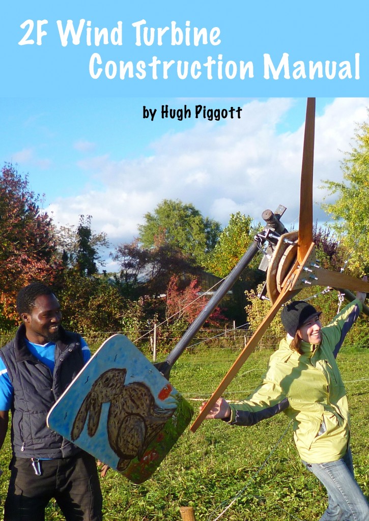
It has taken me a while to finalise my documentation of the 2F design but I have now uploaded an ebook to Smashwords, and hope that in time they will distribute it to Amazon etc. Meantime you can buy it in any digital format you like directly from Smashwords.
I plan to also print some paper copies and offer them for sale in due course.
I apologise for not giving this information away for free. Enterprising readers will presumably find a way to steal it anyway. But bear in mind if/when you do this that I have put untold hours of loving work into preparing this document. Hours that I could have spent doing something rather better paid. I have received abusive messages saying I should not be charging money for this, but given that the price of the book is less than almost any item in the list of materials you will need to build it, I feel that my pricing is not unreasonable.
Have fun! Hugh
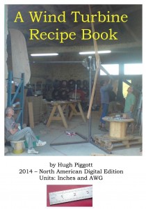
My Wind Turbine Recipe Book comes in two editions: Metric and “English Units” (also known as “Inches” or “North American” edition). I had to publish the English units edition because the 46x30x10mm magnets, and the metric wire sizes that I normally use are not available in the USA. In America generally you will find that Inches prevail, and also the rather limited range of AWG wire sizes. The English Units edition is based on 2″ x 1″ x 1/2″ neo magnets.
 The English units edition is not a simple conversion of the sizes into inches and AWG etc. It is a subtly different set of designs that works with these subtly different magnet and wire sizes. My advice is not to mix the two books although the result will kind of work if you do. Choose one system and follow the recipe for that.
Up to now the English Units edition has only been available in hard copy direct from me and from other outlets in America. Now for the first time I have published it (in fully updated form for 2014) as an ebook (epub and mobi files etc) via Smashwords. In due course it will appear at all ebook stores, Amazon Kindle, Apple, Kobo, scribd, etc… For now you can buy it directly from Smashwords, here.
The $9.99 cost is a little higher than the cost of the 2010 kindle metric edition, but for North American readers I would say it is well worth the difference. Similarly the 2013 metric edition is a better idea than the older 2010 Kindle one, although this 2013 is only available in pdf for now.
| Book title | Hard copy | ebook |
| Wind Turbine Recipe Metric | 2013 | 2013 pdf |
| Wind Turbine Recipe Inches | 2012 | 2014 all |
| 2F construction manual | 2014 all | |
| Windpower Workshop | 2011 | |
| Scrapyard Windpower Realities (classic) | 1992 all |
My new plans for making a 2 metre diameter wind turbine using the more durable ferrite magnets are now available in hard copy form by post from me. It’s the same as the ebook version but printed in 2 columns in a 52 page book.
This will probably be the final edition of my Recipe Book, first published in 2009. Minor changes since last year’s edition and significantly better than the first ebook 2010 edition.
This was removed by scribd for a few days because they thought it was in breach of copyright because they already have the 2013 edition, but I sorted that out now.
I am planning to hold a course here on Scoraig in April. We’ll build and test a wind turbine as usual. Accommodation is provided from Saturday 18th to Saturday 25th April 2015. These will be the arrival and departure days. The course will run for six days from 19th to 24th. Your partner may be able to find accommodation here too without attending the workshop. Please ask for details.
See photos of 2012 course (plus video) , 2013 course and 2014 course. Cost will be £700 including accommodation. I may be able to offer a limited number of student discounts if there are enough people paying full price.
Contact me for more details and to book a place. I do not plan to travel around teaching courses this year as I have mostly done over the last 12 years or so. This may be your only opportunity to be taught by me personally, although there are several other groups worldwide offering courses based on my Recipe Book or derivatives of it.
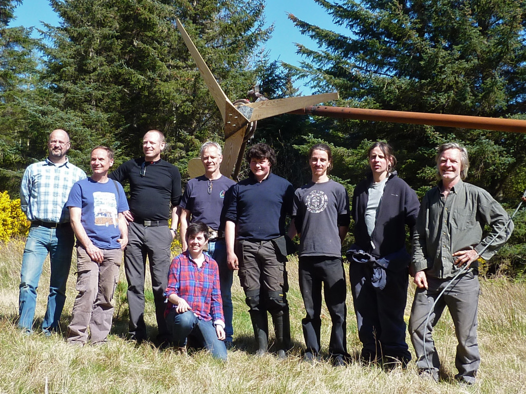
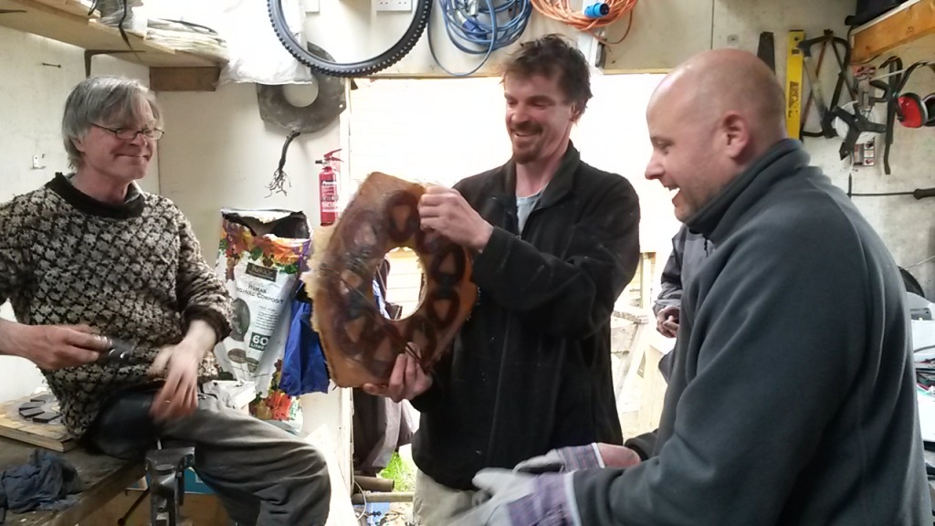
Happy crew
Here is footage from the presentation I made for the Windempowerment Conference in Athens last month. Actually this is a backup that was not used at the conference as I was able to make the same presentation live (and said a whole lot of different things, I think). Anyway this backup version is too long to upload as a single video so I have split it into 3 parts: Scoraig Stories, Alternator Design, and a shorter subsection: Ferrite Magnet Windmill. This last is an intro to my new 2F design document
sorry about the poor sound quality
More about windmills in the old days on Scoraig here
I got asked a question that a lot of people ask me, so I thought it worth answering here.
“Hi Hugh my name is Bill looking through your book A Wind Turbine Recipe Book I am a little confused with the tail vane lower stop. If the tail is allowed to travel 110 degrees it would seem you would be 20 degrees to far in the opposite direction and the blades would never face the wind squarely. Does the tail come off the lower stop during normal operation? What am I missing? Thanks in advance.”
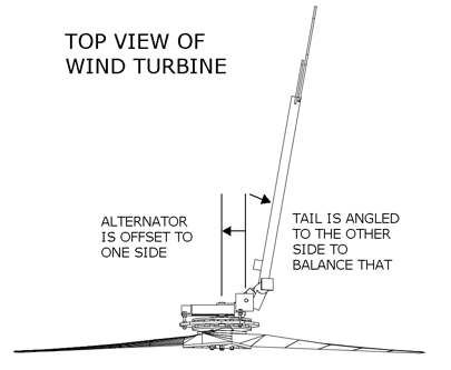
Here is a plan view of the Recipe layout. The alternator frame is mounted onto the yaw bearing off-centre, in order to create a ‘yawing moment’ that tends to swivel the turbine around sideways to the wind. The tail is deliberately angled a little to the opposite side in order to balance this tendency and to keep the turbine facing squarely into the wind under most conditions.
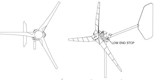
The above picture tells a story. The left hand turbine is the design I used up to 2008. After that I switched the offset to the other side so the machine furls to the left instead of to the right. I will skip the reason for this change here, as it is not very important. But it has been very interesting to watch when there are two machines of the different designs in the same field of view. They often look like the above picture.
We tend to assume that the tail always points downwind. That’s what it’s designed to do, right? But looking at the above picture, this is what you actually see when there are two wind turbines with the same wind direction. The tail vane swings off the downwind direction. It’s very noticeable when they swing in different directions.
It’s not at all unusual to see 20 degrees error between the tail and the wind direction, and often the difference is larger. Why does this happen? To understand it you need to think about the forces on the tail. Before the blades start turning, the tail acts just like a wind vane, but when the blades are spinning they catch a large thrust force that is centred a bit off the centre of the tower-top yaw bearing on which the machine swivels. The purpose of this offset is to make the machine move edge-on to the wind and protect itself from overload in strong winds.
The thrust force is counteracted/balanced by the tail, but it moves a bit sideways first. It’s like a boat settling in the water as you climb in. The boat settles to get more buoyancy. The tail needs a bit of an angle to the wind to create the lift force needed to balance the blades’ thrust. Hence the 20 degree angle in the Recipe design.
I hope this helps explain the logic. There’s a lot to say about furling systems. They are very simple in some ways, and extremely complex in reality, but they do the job.
I never like lifting magnet rotors into the mould. The rotor for the 4F is very heavy, having 20 big ferrite magnets on a 50 cm disk. So I made a handle to lift it. I had to make two of the holes in the mould base a bit big to accommodate the nuts on the ends of the handle studs. Worked really nicely and not hard to do!
I don’t write enough about what goes on here at home on Scoraig so here is a run down on where my electricity comes from. I have two windmills and a collection of solar PV panels. 800 Ah Rolls 4000-series battery and 48 V and two Outback VFX 3 kW inverters.
The big windmill charges the 48 V battery via a couple of heaters in series. We get very little heat in low winds but almost all of the power goes to battery charging with very low cut-in around 60 rpm. As the current increases to (say) 20 A we get about 1000 W to the battery and 300 W of heat. When it reaches 40 A we get 2400 W at the battery (assuming 60V) and 1200 W of heat. The heat (combined with waste heat from cooking) is sufficient for our well insulated house most of the time. I prefer the windmill should not go a lot higher output than that, but it’s turbulent site in NW gales so we do see much higher surge outputs and there is trip that brings in extra heaters as a braking load when the voltage reaches 140 V (7.5 kW). I had a bad accident with this windmill (tower buckling) in a bad storm last January, and nowadays it is governed to about 1 kW average into the battery. It looks lazy but it does all we need.
The smaller windmill is an AWP from Zimbabwe but the blades are locally made from wood. It runs through an MPPT controller (I have tested both Classic and Tristar) that enhances the peak output to about 1500 watts.
The Solar array consists of 4 strings (pairs) of big 240 Wp 30 V modules and 2 strings (fours) of little 80 Wp 17 V modules totalling about 2.5 kWp. These feed into the battery, and surplus power (wind and solar) is dumped to hot water using a Tristar PWM diversion load controller. When the water tank is hot, the excess power is diverted to AC heating loads using a phase control SSR. We also have some evacuated tubes for hot water.
Electricity consumption is running at about 6500 kWh per year. (The UK domestic average is 4200 but I also run my business and the extended family house next door). We do most of our cooking with electricity, using a kettle, toaster, microwave, induction hob and halogen oven. We also recently replaced the gas oven with a big electric oven.
When the wind stops and there is not much sunlight the batteries get a bit of a fright, and I have to fire up a diesel generator. This has run for an average of 150 hours per year over the last two years, feeding about 2-3 kW of power into the system.
I am planning to hold a course here on Scoraig in April. We’ll build and test a wind turbine as usual. Accommodation is provided from Saturday 23rd to Saturday 30th April 2016. These will be the arrival and departure days. The course will run for six days from 24th to 29th. Your partner may be able to find accommodation here too without attending the workshop. Please ask for details.
See photos of 2012 course (plus video) , 2013 course, 2014 course and last year. Cost will be £750 including accommodation. I may be able to offer a limited number of student discounts if there are enough people paying full price.
Contact me for more details and to book a place. I do not plan to travel around teaching courses any more as I already did that for 12 years or so. This may be your only opportunity to be taught by me personally, although there are several other groups worldwide offering courses based on my Recipe Book or derivatives of it.
From 23rd-29th April 2016 i hosted a workshop here at Scoraig.
Seven “students”. Co-instructor Jonathan from Austria.
Project was 2.4m diameter 24-V battery charging turbine from the Recipe Book. See also the pdf guide to welding this machine. Mostly it was pretty standard, but we did a new magnet rotor mould design with wood-screws that adjust the height of the disk within the casting. This was the result of a group brainstorm session.
Accommodation at “Drift Wood” with all meals provided.
Here are some photos of the week’s events. Mostly mine but some from Jonathan and Mark, thanks!
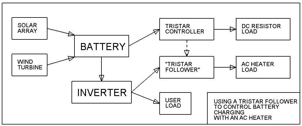
I have just added a page about how to build a Tristar Follower (as I call it) that uses an AC heater connected to your inverter to dump surplus power (usually into heating water) when the battery does not need it. It uses phase control to do this smoothly.
It’s a pretty simple electronics project with only a handful of passive components to wire up. I have built quite a few of them now and they work nicely. The Tristar is good at deciding when to dump power but DC loads are not so useful, whereas an AC heater in your water tank can produce a lot of hot water without having to burn any fuel.
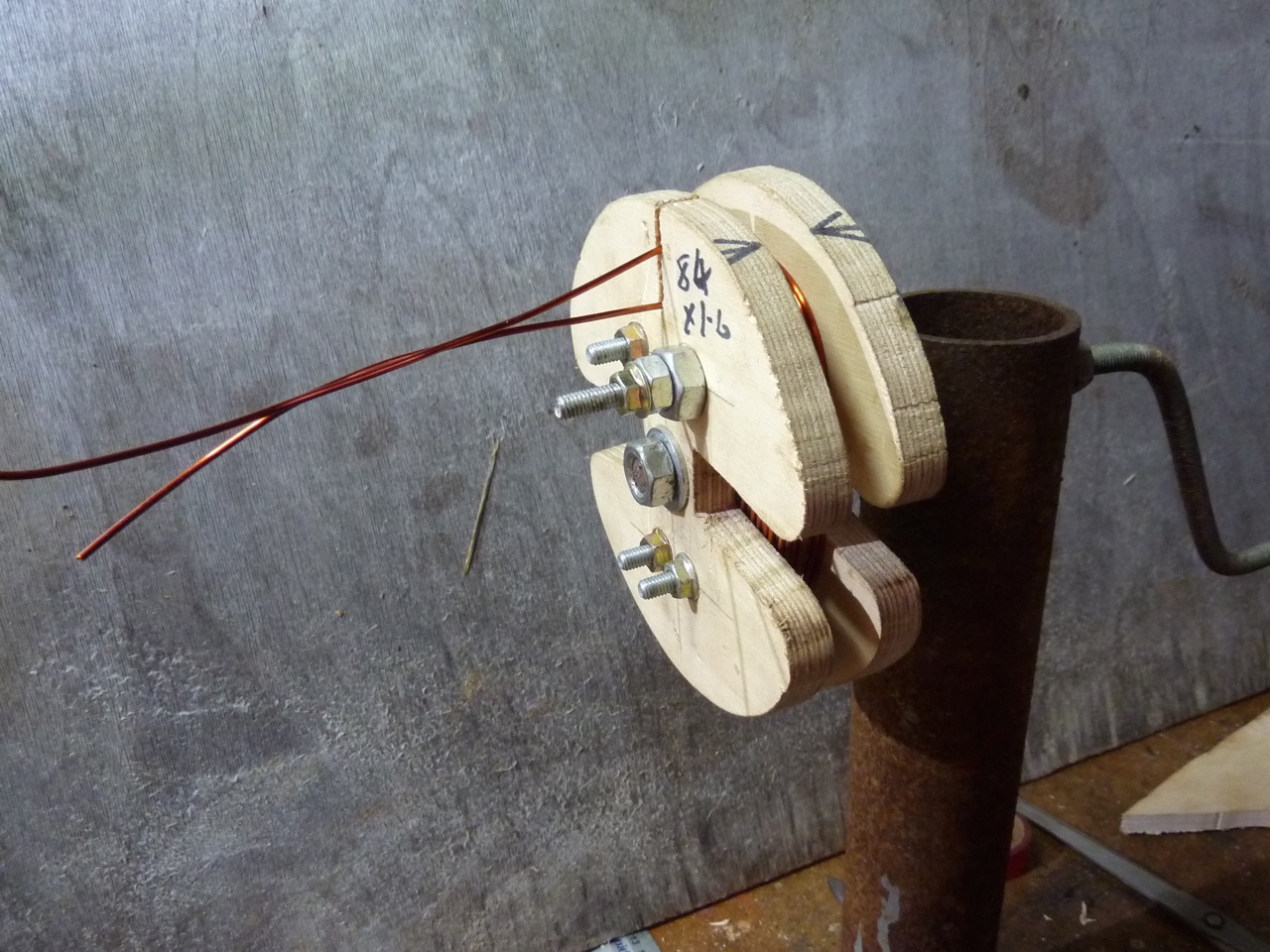
I don’t put enough of the stuff that goes on in my own workshop onto this blog so here is a workshop session where I am winding a coil for a repair for a big machine, and I talk through the process a bit as I go.
The other day I had to take this 2F windmill down because it had stopped working.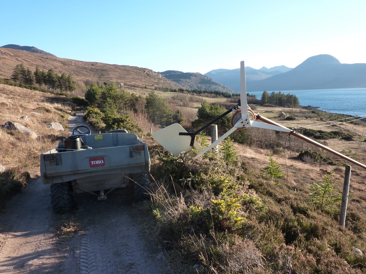 Turning slowly as if on the brake. It’s a few years old and I thought most likely the flexible wiring inside the tower had got twisted up a bit and somehow shorted out, although the wires did not look that bad a ground level.
I was pretty shocked when I saw it close up, because the plywood had somehow got shattered at the front. 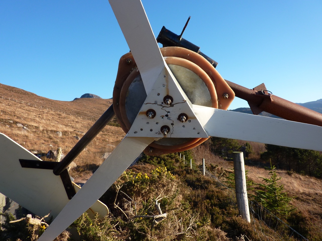 Birch plywood is very strong, but I suppose I was pushing it a bit to use 9mm ply here. It’s not the oldest 2F on Scoraig using that plywood but it definitely taught me something. Always more to learn!
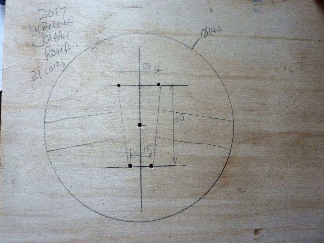
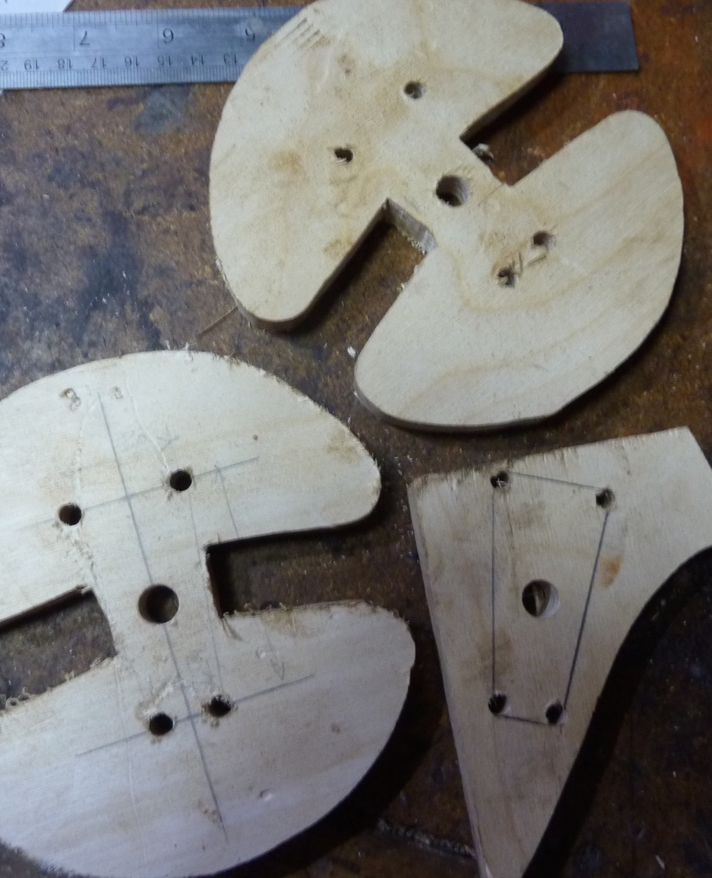
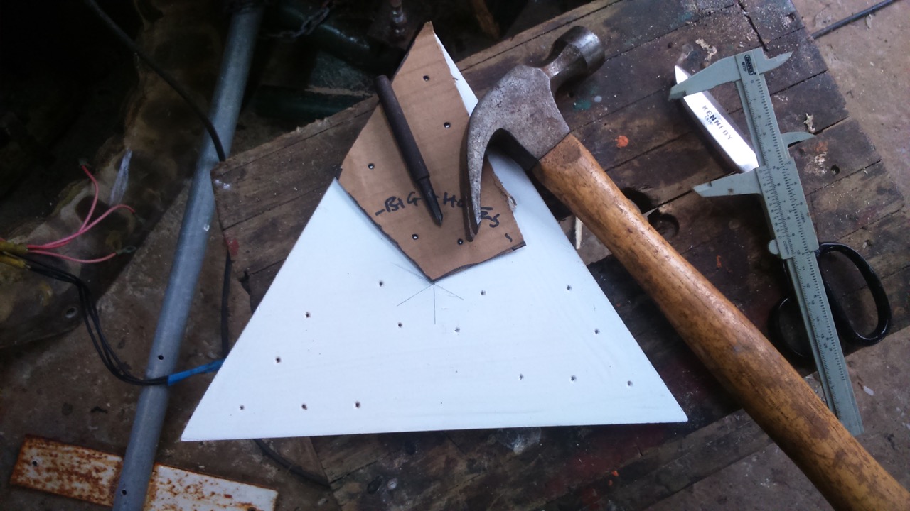
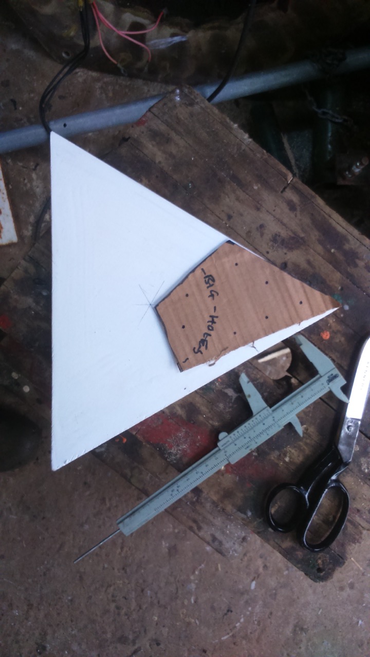
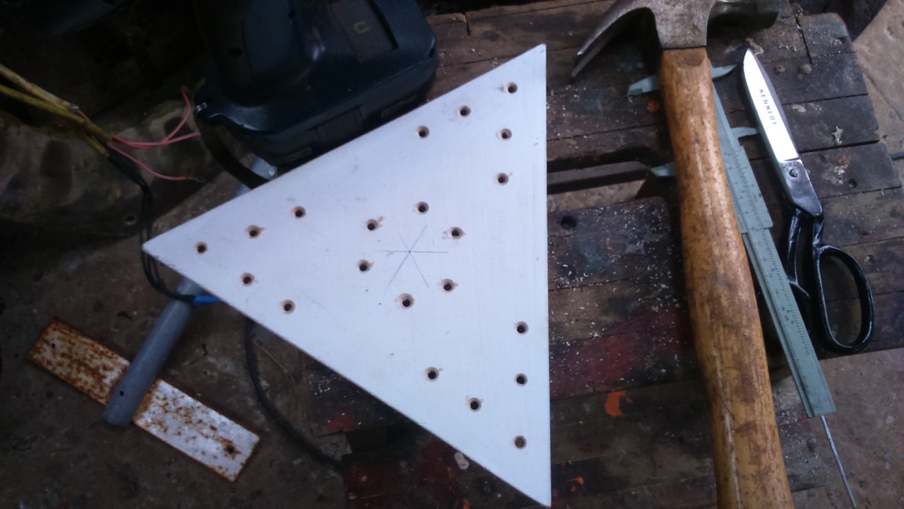
I replaced the 9mm with 12mm birch. I figured out a quick way to lay out the screw holes in the plywood so they are neat and symmetrical, and avoid the bolt holes for the mounting studs. I used a cardboard template that matches the shape of the contact area between blade and ply. (Click to see larger images.)
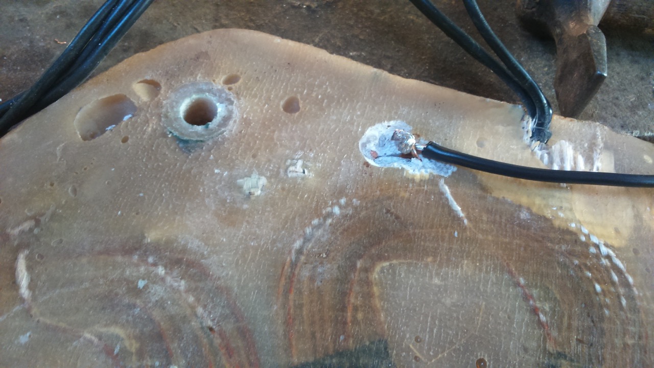
Punching through the dots on the cardboard gave me my hole centres for drilling. Next I went looking for the shorted wiring. But I found to my horror that the alternator was “braked” even when totally disconnected from the wiring, so the short was internal. Maybe I needed to make a new stator?
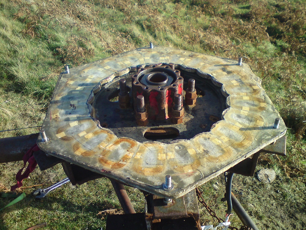
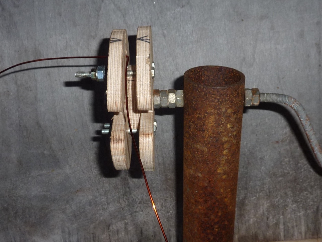
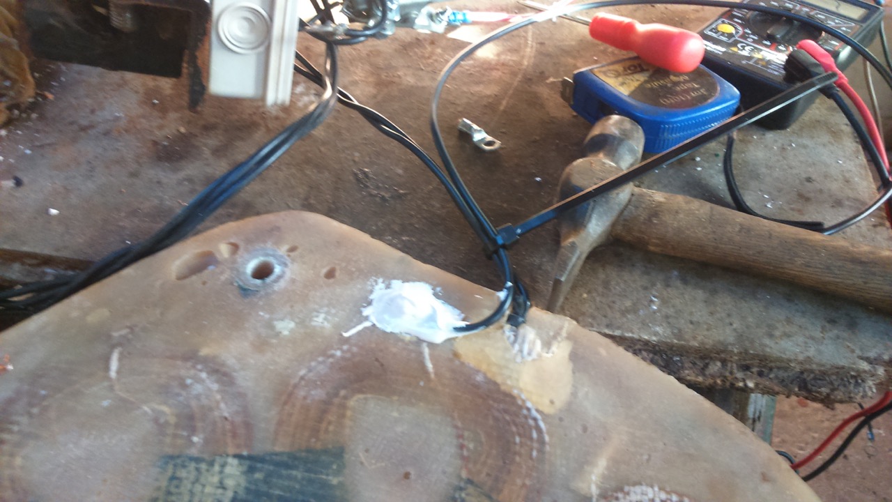
First I set to work to find the location of the short. I used a battery, a magnet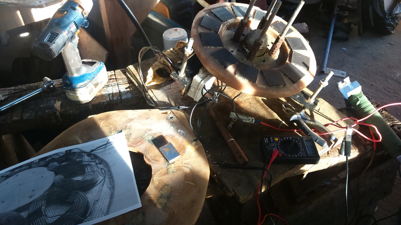 and a photo that I miraculously found of the stator before it was cast (back in 2013).
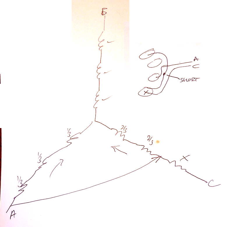
Passing current through the coils between each pair of wires gives rise to a pattern of attraction and repulsion of the magnet in the winding that reveals where the current is going. (Usually this will be “push, pull, nothing, push, pull, nothing, push, pull, nothing.”) One pair of wires gave rise to a very strong field in just one coil and the photo revealed where the short must be between the output wire off a neighbouring coil and a series connection from that coil to the next.
The fact that it was a fault on an incoming wire meant I could simply cut that wire and make a new incoming connection to the first coil in phase A where the wire comes close to the surface of the casting to enter the coil. So there was not too much digging around to do in the resin (using a drill and a gouge).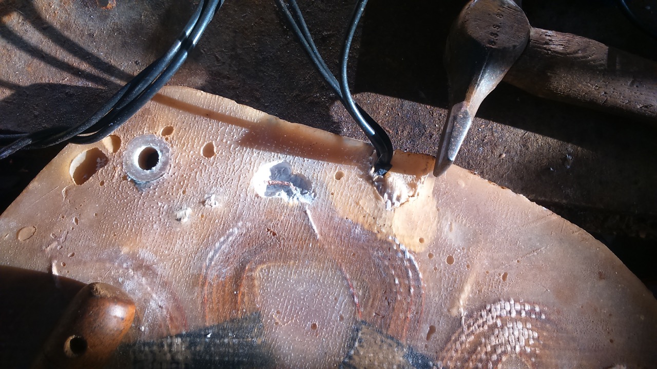
That was pretty lucky, and a quick solder joint had it all sorted out.
Balanced the blades, greased the bearings, untwisted the tower wires with a cordless drill and got the machine back into action after a relatively painless repair considering how much worse it could have been!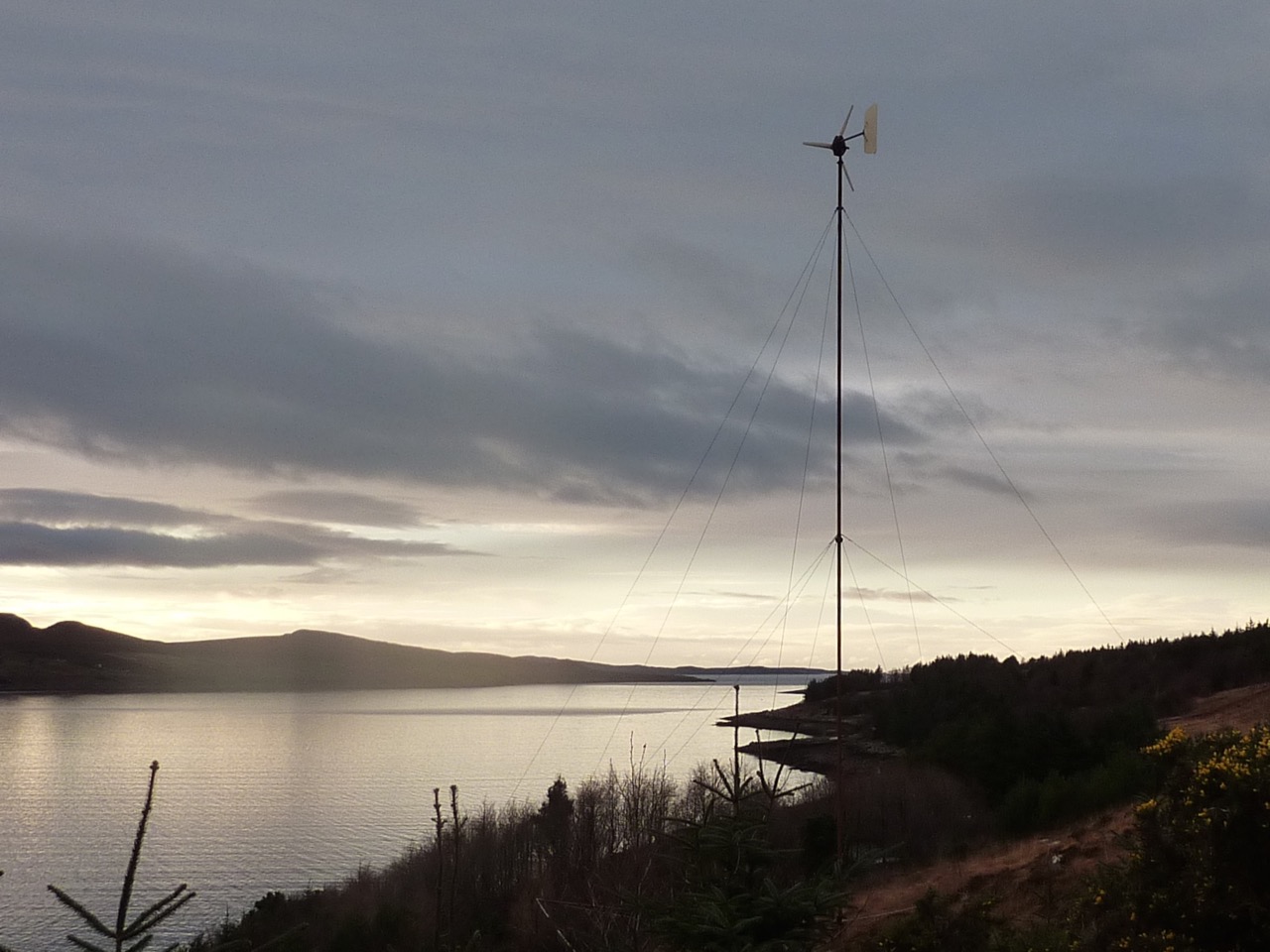
Not a breath of wind of course.